Thursday, November 28, 2013

Satellite Gear Modding:Adding fans to AZAmerica s900 sat reciever + Ibox

The both of them run really hot, hands into matter, ordered two flat vga fans from aliexpress (THIS).

Az America s900:


Disconnect all equipment from AC !!!!!

Take out the cover, and disconnect the power source, and all other cable attached to work comfortably. Here we go!

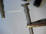
 Once opened just locate some pins that can provide some acceptable voltage. See next picture, I found a 5v and ground. (5v will garantee a smooth operation)
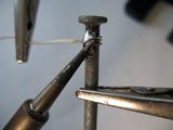
 I simply pinched into the cables, before the entered the next connector, and tested. After that, I just simply attached up from the heat sink.

Always test, check, and then re fit all back togheter.


IBOX:

Disconnect all equipment from AC !!!!!
Simple 4 screw on the back of the box. 
Disassemble and you get this, there's the tiny heat sink.

The power jack is ideal, since ibox runs on 12v (check you power source), look at the back of the board, and use one of the holes to pass the cables to the back.
Once tested with which pins does it work, solder and test. Just to keep it on the safe side, you can add some glue-gun in order to isolate.
Once in position, see that the blades does not hit any component on the top board. I used some screws to attached the fan into the top cover.

Put the box together, and ready to go, if the fan is too noisy you can add a 10k potentiometer or a resistance.


Monday, November 18, 2013

Anti Rain flood system - Arduino water pump Automation

Been having some trouble at home due to a poorly designed water drain, heavy rains just put at risk overflowing with the drains capacity, I got some problems after getting some water inside my house so I took matters into my own.

The idea is to have and automated system to drain the water out of the "warning zone" out to another place, another idea is to harvest this water if you have the place to store some big containers.

Target: have a fully automated system that can measure the water level and in case the level is near the "warning" level, it activates a water pump to lower the level. As a secondary target the idea is to see the level in real time through a web page.

Bill Of Materials:

ItemPictures
Arduino (using UNO, will port to pro mini)

Network shield ENC28j60

Distance measuring module HC-SR04

5v relay module

Old wireless repeater DLINK


Water pump 1/2 horsepower

Enclosing box


Power cord & extension

Hose & quick connectors connector
Pvc tube
Ping pong ball
General materials: glue, soldering iron, electrical tools


Here are basic schematics for this project:

Tube assembly:
Tube assembly
Block Diagram:
Housing block diagram
Phases for this project:

Phase 1: get the basic software working. Code the basics for the arduino to measure the distance and upon threshold, activate relay.

Phase 2: building the container for outdoors. Using an hermetic plastic container (a big tupperware :) ), fit all the parts in there, water proofing it, build the pvc tube with the sensor container.

Phase 3: initial testing, a data analysis.

Phase 4: attach wireless repeater in client mode, using network module to: monitor system from web, upload measurements information to mysql database.

Stay tuned for how the project evolves.

Wednesday, November 13, 2013

New toys! Lets gets started!

New toys arrived

Last shipment arrived to I can finish an automated pump system, measuring water level with a HC-sr04 sensor module. IMG 0880 Some other goodies also arrived to make projects work more tidy.

Monday, September 23, 2013

Embedding an RFID tag into a phone: not so simple

Embedding an RFID tag into a phone: not so simple

Inspired by this site I decided to have one of my rfid tag embedded into my iphone 4s, as to use is a master key on my future developments.

I started dissolving the tag with acetone, and while dissolving I started to read some documents on RFID antennas (link) great document, covers from the basics!

Let me tell you a couple of things about embeding

1) I dissolved 2 tags.... first one, stopped working.


2) The one I dissolved does not fit, and cant tear it apart. So, I'm not so happy, though this was going to be easy.

Working dissolved tag:

Not working tag:


Will keep update on the progress or abandonment of this project (quoting Murphy: If at first you don't succeed destroy all evidence that you ever tried. )

Saturday, September 7, 2013

Last goodies arrivedfrom china

Dx sure takes time in delivering nice Arduino and DIY toys in my country, but at last!!!!

Active Buzzer (DC 5V): simple great, to add some noise to our gadgets. Link

RF ID Proximity Token Tag Key Keyfobs Keychain - Blue + Silver (10 PCS): I've always wanted to start to explore on RFID, this is a great simple, cheap starting point. Link


Intelligent ID Card USB Reader: The crown jewel. =) Link This is a really cool item, this works as an input like a keyboard when it detects an RFID tag. 


This is my plan in mind, I was looking at this site. I wanted to start experimenting with replacing the antenna for a different one that could fit into a 1meter/5cm diameter PVC tube.

Stay tuned =)

Photosensitive Sensor Module Testing

I got this from DX: MN-EB-PTCMN Photosensitive Sensor Module - Orange.


Basically a photocell, after some investigation I got some help from this site, the code showed here is

 1
 2
 3
 4
 5
 6
 7
 8
 9
10
11
12
13
14
15
16
17
18
19
20
21
22
23
24
25
26
27
28
29
30
31
32
33
34
int photoRPin = 0; 
int minLight;
int maxLight;
int lightLevel;
int adjustedLightLevel;

void setup() {
 Serial.begin(9600);
 
 //Setup the starting light level limits
 lightLevel=analogRead(photoRPin);
 minLight=lightLevel-20;
 maxLight=lightLevel;
}

void loop(){
 //auto-adjust the minimum and maximum limits in real time
 lightLevel=analogRead(photoRPin);
 if(minLight>lightLevel){
 minLight=lightLevel;
 }
 if(maxLight<lightLevel){
 maxLight=lightLevel;
 }
 
 //Adjust the light level to produce a result between 0 and 100.
 adjustedLightLevel = map(lightLevel, minLight, maxLight, 0, 100); 
 
 //Send the adjusted Light level result to Serial port (processing)
 Serial.println(adjustedLightLevel);
 
 //slow down the transmission for effective Serial communication.
 delay(50);
}

This code is property of Scott please take a look at his site for more interesting posts.

Thanks to this excellent piece of code you get a reading from 0-100 of the light sensed. Cool to build on to another things.

Here's an image of the serial console of the reading.

Heres a basic of the circuit, basic 3 pins (ground, 5v, signal(this goes to analog 0 in arduino))


Monday, September 2, 2013

Rfid and other stuff

PAt last more items have arrived:

Channel 5V Relay Module:

Meeeno MN-EB-PTCMN Photosensitive Sensor Module:


The true jewel here: RFID-RC522 RF IC Card Sensor Module


Arduino tvout shield

This a simple one but here's my tvou shield for arduino.


It's based on the documents placed here. Pretty cool site, offers exampled and all necessary data to make it work.

Since I'm more of a shield guy, here is the fritzing diagram and pcb.


Friday, August 23, 2013

New arduino toys!! Finally arrived

After a lot of waiting for the post office new things arrived!!

TSOP1838 IR Infrared 37.9Khz Receiver (18m-Range / 2.7~5.5V)

SD Card Reading Writing Module for Arduino (Works with Official Arduino Boards)

ENC28J60 Ethernet LAN / Network Module for 51 AVR STM32 LPC

Soil Humidity Moisture Detection Sensor Module - Blue + Black + White

66 days waiting finally got the tools to resume working on the projects!

Thursday, August 1, 2013

Organization ideas

Great idea for cables using a box and cardboard tubes.

Ziplocks for cables and  Big tupperware for the ziplocks

Plastic organizers


How do you keepup with you gadget mess??

Saturday, June 29, 2013

GameBoy Flashbacks!


A true flashback into the 80s and early 90s.

I finally got my usb 64m smart card from Kitsch-bent its a great site, and the after sales services are great, I had some doubts due to delays in shipping and he was great!

So that opens a range of opportunities to load legal roms, and use gameboy for new experiments.

Also, digging though some boxes, found a complete GBC set.

Great news!!!


Monday, June 17, 2013

ArduGarden (Gardening assited by arduino) Vol II temporal

Few days with a lot of fast protoyping, pardon the cheap materials and the poor finishing.

I added a Small lcd display to see all data.

Yup, I over watered my tomato seeds.

I ended up using a nokia 5100 lcd (thats why the temporal) instead if what I had planned: a lcd 16x2. (glitch: I got only one line out of the two, to work with black boxes showing using the 16x2, and could not fix it right away) Internet suggest its wiring... I triple checked and nothing.

I also own a 16x2 shield, but future plans will include ab outdoor housing and wouldnt want to waste a graphic display on this.

Heres the code: have fun!!

//Coded by Alejandro Zanotti
//Based on the ideas Shown on this post http://forum.arduino.cc/index.php/topic,37975.0.html and this tutorial http://www.botanicalls.com/archived_kits/twitter/
//Version 1.0 
//Date 17 Jun 2013
//lcd start
#define PIN_SCE   7
#define PIN_RESET 6
#define PIN_DC    5
#define PIN_SDIN  4
#define PIN_SCLK  3

#define LCD_C     LOW
#define LCD_D     HIGH

#define LCD_X     84
#define LCD_Y     48

static const byte ASCII[][5] =
{
 {0x00, 0x00, 0x00, 0x00, 0x00} // 20  
,{0x00, 0x00, 0x5f, 0x00, 0x00} // 21 !
,{0x00, 0x07, 0x00, 0x07, 0x00} // 22 "
,{0x14, 0x7f, 0x14, 0x7f, 0x14} // 23 #
,{0x24, 0x2a, 0x7f, 0x2a, 0x12} // 24 $
,{0x23, 0x13, 0x08, 0x64, 0x62} // 25 %
,{0x36, 0x49, 0x55, 0x22, 0x50} // 26 &
,{0x00, 0x05, 0x03, 0x00, 0x00} // 27 '
,{0x00, 0x1c, 0x22, 0x41, 0x00} // 28 (
,{0x00, 0x41, 0x22, 0x1c, 0x00} // 29 )
,{0x14, 0x08, 0x3e, 0x08, 0x14} // 2a *
,{0x08, 0x08, 0x3e, 0x08, 0x08} // 2b +
,{0x00, 0x50, 0x30, 0x00, 0x00} // 2c ,
,{0x08, 0x08, 0x08, 0x08, 0x08} // 2d -
,{0x00, 0x60, 0x60, 0x00, 0x00} // 2e .
,{0x20, 0x10, 0x08, 0x04, 0x02} // 2f /
,{0x3e, 0x51, 0x49, 0x45, 0x3e} // 30 0
,{0x00, 0x42, 0x7f, 0x40, 0x00} // 31 1
,{0x42, 0x61, 0x51, 0x49, 0x46} // 32 2
,{0x21, 0x41, 0x45, 0x4b, 0x31} // 33 3
,{0x18, 0x14, 0x12, 0x7f, 0x10} // 34 4
,{0x27, 0x45, 0x45, 0x45, 0x39} // 35 5
,{0x3c, 0x4a, 0x49, 0x49, 0x30} // 36 6
,{0x01, 0x71, 0x09, 0x05, 0x03} // 37 7
,{0x36, 0x49, 0x49, 0x49, 0x36} // 38 8
,{0x06, 0x49, 0x49, 0x29, 0x1e} // 39 9
,{0x00, 0x36, 0x36, 0x00, 0x00} // 3a :
,{0x00, 0x56, 0x36, 0x00, 0x00} // 3b ;
,{0x08, 0x14, 0x22, 0x41, 0x00} // 3c <
,{0x14, 0x14, 0x14, 0x14, 0x14} // 3d =
,{0x00, 0x41, 0x22, 0x14, 0x08} // 3e >
,{0x02, 0x01, 0x51, 0x09, 0x06} // 3f ?
,{0x32, 0x49, 0x79, 0x41, 0x3e} // 40 @
,{0x7e, 0x11, 0x11, 0x11, 0x7e} // 41 A
,{0x7f, 0x49, 0x49, 0x49, 0x36} // 42 B
,{0x3e, 0x41, 0x41, 0x41, 0x22} // 43 C
,{0x7f, 0x41, 0x41, 0x22, 0x1c} // 44 D
,{0x7f, 0x49, 0x49, 0x49, 0x41} // 45 E
,{0x7f, 0x09, 0x09, 0x09, 0x01} // 46 F
,{0x3e, 0x41, 0x49, 0x49, 0x7a} // 47 G
,{0x7f, 0x08, 0x08, 0x08, 0x7f} // 48 H
,{0x00, 0x41, 0x7f, 0x41, 0x00} // 49 I
,{0x20, 0x40, 0x41, 0x3f, 0x01} // 4a J
,{0x7f, 0x08, 0x14, 0x22, 0x41} // 4b K
,{0x7f, 0x40, 0x40, 0x40, 0x40} // 4c L
,{0x7f, 0x02, 0x0c, 0x02, 0x7f} // 4d M
,{0x7f, 0x04, 0x08, 0x10, 0x7f} // 4e N
,{0x3e, 0x41, 0x41, 0x41, 0x3e} // 4f O
,{0x7f, 0x09, 0x09, 0x09, 0x06} // 50 P
,{0x3e, 0x41, 0x51, 0x21, 0x5e} // 51 Q
,{0x7f, 0x09, 0x19, 0x29, 0x46} // 52 R
,{0x46, 0x49, 0x49, 0x49, 0x31} // 53 S
,{0x01, 0x01, 0x7f, 0x01, 0x01} // 54 T
,{0x3f, 0x40, 0x40, 0x40, 0x3f} // 55 U
,{0x1f, 0x20, 0x40, 0x20, 0x1f} // 56 V
,{0x3f, 0x40, 0x38, 0x40, 0x3f} // 57 W
,{0x63, 0x14, 0x08, 0x14, 0x63} // 58 X
,{0x07, 0x08, 0x70, 0x08, 0x07} // 59 Y
,{0x61, 0x51, 0x49, 0x45, 0x43} // 5a Z
,{0x00, 0x7f, 0x41, 0x41, 0x00} // 5b [
,{0x02, 0x04, 0x08, 0x10, 0x20} // 5c ¥
,{0x00, 0x41, 0x41, 0x7f, 0x00} // 5d ]
,{0x04, 0x02, 0x01, 0x02, 0x04} // 5e ^
,{0x40, 0x40, 0x40, 0x40, 0x40} // 5f _
,{0x00, 0x01, 0x02, 0x04, 0x00} // 60 `
,{0x20, 0x54, 0x54, 0x54, 0x78} // 61 a
,{0x7f, 0x48, 0x44, 0x44, 0x38} // 62 b
,{0x38, 0x44, 0x44, 0x44, 0x20} // 63 c
,{0x38, 0x44, 0x44, 0x48, 0x7f} // 64 d
,{0x38, 0x54, 0x54, 0x54, 0x18} // 65 e
,{0x08, 0x7e, 0x09, 0x01, 0x02} // 66 f
,{0x0c, 0x52, 0x52, 0x52, 0x3e} // 67 g
,{0x7f, 0x08, 0x04, 0x04, 0x78} // 68 h
,{0x00, 0x44, 0x7d, 0x40, 0x00} // 69 i
,{0x20, 0x40, 0x44, 0x3d, 0x00} // 6a j 
,{0x7f, 0x10, 0x28, 0x44, 0x00} // 6b k
,{0x00, 0x41, 0x7f, 0x40, 0x00} // 6c l
,{0x7c, 0x04, 0x18, 0x04, 0x78} // 6d m
,{0x7c, 0x08, 0x04, 0x04, 0x78} // 6e n
,{0x38, 0x44, 0x44, 0x44, 0x38} // 6f o
,{0x7c, 0x14, 0x14, 0x14, 0x08} // 70 p
,{0x08, 0x14, 0x14, 0x18, 0x7c} // 71 q
,{0x7c, 0x08, 0x04, 0x04, 0x08} // 72 r
,{0x48, 0x54, 0x54, 0x54, 0x20} // 73 s
,{0x04, 0x3f, 0x44, 0x40, 0x20} // 74 t
,{0x3c, 0x40, 0x40, 0x20, 0x7c} // 75 u
,{0x1c, 0x20, 0x40, 0x20, 0x1c} // 76 v
,{0x3c, 0x40, 0x30, 0x40, 0x3c} // 77 w
,{0x44, 0x28, 0x10, 0x28, 0x44} // 78 x
,{0x0c, 0x50, 0x50, 0x50, 0x3c} // 79 y
,{0x44, 0x64, 0x54, 0x4c, 0x44} // 7a z
,{0x00, 0x08, 0x36, 0x41, 0x00} // 7b {
,{0x00, 0x00, 0x7f, 0x00, 0x00} // 7c |
,{0x00, 0x41, 0x36, 0x08, 0x00} // 7d }
,{0x10, 0x08, 0x08, 0x10, 0x08} // 7e ←
,{0x78, 0x46, 0x41, 0x46, 0x78} // 7f →
};

void LcdCharacter(char character)
{
  LcdWrite(LCD_D, 0x00);
  for (int index = 0; index < 5; index++)
  {
    LcdWrite(LCD_D, ASCII[character - 0x20][index]);
  }
  LcdWrite(LCD_D, 0x00);
}

void LcdClear(void)
{
  for (int index = 0; index < LCD_X * LCD_Y / 8; index++)
  {
    LcdWrite(LCD_D, 0x00);
  }
}

void LcdInitialise(void)
{
  pinMode(PIN_SCE, OUTPUT);
  pinMode(PIN_RESET, OUTPUT);
  pinMode(PIN_DC, OUTPUT);
  pinMode(PIN_SDIN, OUTPUT);
  pinMode(PIN_SCLK, OUTPUT);
  digitalWrite(PIN_RESET, LOW);
  digitalWrite(PIN_RESET, HIGH);
  LcdWrite(LCD_C, 0x21 );  // LCD Extended Commands.
  LcdWrite(LCD_C, 0xB1 );  // Set LCD Vop (Contrast). 
  LcdWrite(LCD_C, 0x04 );  // Set Temp coefficent. //0x04
  LcdWrite(LCD_C, 0x14 );  // LCD bias mode 1:48. //0x13
  LcdWrite(LCD_C, 0x0C );  // LCD in normal mode.
  LcdWrite(LCD_C, 0x20 );
  LcdWrite(LCD_C, 0x0C );
}

void LcdString(char *characters)
{
  while (*characters)
  {
    LcdCharacter(*characters++);
  }
}

void LcdWrite(byte dc, byte data)
{
  digitalWrite(PIN_DC, dc);
  digitalWrite(PIN_SCE, LOW);
  shiftOut(PIN_SDIN, PIN_SCLK, MSBFIRST, data);
  digitalWrite(PIN_SCE, HIGH);
}
//lcd fin

const int sensorpin=0;
int moisture=0;
int lastWaterVal=0;
int led = 8;

#define MOIST 450 // minimum level of satisfactory moisture
#define DRY 350  // maximum level of tolerable dryness
#define SOAKED 600 // minimum desired level after watering
#define WATERING_CRITERIA 100 // minimum change in value that indicates watering


void setup (){
  pinMode(led, OUTPUT); 
  Serial.begin(115200);
  Serial.println("Soil Moisture Module v1: Loaded");
  Serial.println();
  LcdInitialise();
  LcdClear();
  LcdString("Soil Moisture Module v1: Loaded");

  
}

void loop (){
  moisture=analogRead(sensorpin);

    LcdInitialise();
        LcdClear();

      if (moisture >= SOAKED  &&  lastWaterVal < MOIST) {
        Serial.println(moisture);
       // LcdString(moisture);
        digitalWrite(led, LOW);
        Serial.println("Thank you for watering me!");
        LcdString("Thank you for watering me! :D");  
      }
      else if  (moisture >= SOAKED  &&  lastWaterVal >= MOIST ) {
        Serial.println(moisture);
      //  LcdString(moisture);
        digitalWrite(led, HIGH);
        delay (800);
        digitalWrite(led, LOW);
        Serial.println("You over watered me");

        LcdString("You over watered me :(");
      }
      else if  (moisture < SOAKED  &&  lastWaterVal < MOIST ) {
        Serial.println(moisture);
       // LcdString(moisture);
        digitalWrite(led, HIGH); 
        Serial.println("You didn't water me enough");

        LcdString("You didn't water me enough");   
      }
     
    lastWaterVal = moisture; // record the watering reading for comparison next time this function is called

  delay (5000);
}


Saturday, June 15, 2013

ArduGarden (Gardening assited by arduino) Vol I

Simple idea to assist gardening projects using arduino: get moisture, temperature and other measurements and get alarms, display even use them via networking.

This first step attempted and succeded in getting moisture readings of the soil.

Parts needed:

  • 2 galvenized nails.
  • Wires
  • Arduino 1
  • 1 10k ohm resistor
  • 1 100 ohm resistor
  • Usual tools: clipper, soldering iron.

Step 1 Prepare the nails.

MOISTURE PROBES (AWESOME IDEA TAKEN FROM HERE)
You will need 2 nails that will act as soil moisture probes. You can use any kind of conductive nail that you have lying around, but we recommend using galvanized, hot dipped nails, which are more resistant to corrosion.


-Wrap the wire around the nail and be sure to take the time to heat up the nail as opposed to just heating up with wire and spreading the solder on the wire alone.  This prevents the wire from fusing with the nail and provides an opportunity for the wire to slip off of the nail.
-You'll know that the wire is hot once you touch the solder to the nail and it begins to flow. 
-Work your way around the entire nail connecting the wire.

Note: We are still looking for a better metal that doesn't degrade because of electrolysis.  If you have any suggestions please shoot them our way.

Step 2 Circuits


I based my idea on this:
Thanks ROB, check his blog for more info.
The 2222N transistor pinout goes like this:


Step 3 Software


//Coded by Alejandro Zanotti
//Based on the ideas Shown on this post http://forum.arduino.cc/index.php/topic,37975.0.html and this tutorial http://www.botanicalls.com/archived_kits/twitter/
//Version 1.0 
//Date 15 Jun 2013

const int sensorpin=0;
int moisture=0;
int lastWaterVal=0;

#define MOIST 450 // minimum level of satisfactory moisture
#define DRY 350  // maximum level of tolerable dryness
#define SOAKED 600 // minimum desired level after watering
#define WATERING_CRITERIA 100 // minimum change in value that indicates watering


void setup (){
  Serial.begin(115200);
  Serial.println("Soil Moisture Module v1: Loaded");
  Serial.println();
}

void loop (){
  moisture=analogRead(sensorpin);
  
      if (moisture >= SOAKED  &&  lastWaterVal < MOIST) {
        Serial.println(moisture);
        Serial.println("Thank you for watering me!");  
      }
      else if  (moisture >= SOAKED  &&  lastWaterVal >= MOIST ) {
        Serial.println(moisture);
        Serial.println("You over watered me");
      }
      else if  (moisture < SOAKED  &&  lastWaterVal < MOIST ) {
        Serial.println(moisture);
        Serial.println("You didn't water me enough");   
      }
     
    lastWaterVal = moisture; // record the watering reading for comparison next time this function is called
   

  delay (5000);
}

Actual pictures of it working:


Serial monitor: